Whole Home Performance Verified™ Mixed-Humid Climate Case Study

Whole Home Performance Verified™ Case Study
HVAC 2 Home Performance logo
Mossy Ridge Construction LLC logo
Hagglund Residence • Franklin, Tennessee

Whole Home Performance Verified™
Case Study

The HVAC system was designed for the house. The house was designed for the HVAC system. Final commissioning will verify the installed systems against the design intent.

Whole Home Performance Verified™ connects enclosure, HVAC design, installation accountability, commissioning, humidity control, and ERI modeling into one builder-facing certification path.
Whole Home Performance Verified case study feature image
Projected ERI Score
49

Pass against the 2024 IECC R-406 path, with maximum allowed ERI 50.

19.3%better thermal conductance than code baseline
1.0ACH50 target / 555 CFM50 basis
3 tons2-ton first floor + 1-ton second floor GREE inverter systems
J/S/Dverified design workflow, not just filed paperwork

The point is not “code bad.” The point is “submitted is not verified.”

This project is being developed through the Whole Home Performance Verified™ workflow, connecting HVAC design, ERI energy modeling, IAQ strategy, commissioning planning, airflow verification, and measured field performance targets into one integrated residential system. Final verification metrics, commissioning data, and benchmark results will be added as the project progresses through testing and validation.

A submitted design is not the same as a verified design.

That is the whole case study: code creates a compliance record; VERIFIED™ creates a performance accountability path.

Code compliance pathway

Code tells you what passes.

Design documents may be submitted and filed, but the installed HVAC system can still drift from the original intent through substitutions, duct routing changes, enclosure changes, missed airflow targets, or incomplete commissioning.

Hagglund WHPV™ pathway

Verification shows what performs.

DESIGN VERIFIED™, INSTALLED PER DESIGN™, and PERFORMANCE VERIFIED™ connect the submitted design, the actual building, the equipment, the ducts, the controls, and the measured outcome as final commissioning is completed.

CategoryTypical compliance processHagglund VERIFIED™ process
Design documentsSubmitted for compliance and filingReviewed as design intent and connected to installed performance
Manual J/S/DMay be required or submitted, depending on jurisdiction and scopeVerified J/S/D workflow tied to the actual home, equipment, duct system, and room airflow
Code reviewPrimarily confirms minimum complianceValidates that the HVAC design matches the home being built
HVAC designThe AC is designed for the house on paperThe house and AC are designed for each other, then field-verified together during commissioning
EquipmentBrand and tonnage often drive the conversationValue-conscious GREE inverter equipment is elevated through design and verification
AirflowDuct design may be submitted but not deeply field-verifiedRoom-by-room CFM targets are part of the verification path
HumidityOften left to cooling runtimeVentilating dehumidifier + Ecobee controls + optional HAVEN layer
CommissioningStartup does not equal verified performancemeasureQuick® commissioning supports PERFORMANCE VERIFIED™ validation
Builder riskPasses inspection, but outcomes may still varyPredictable comfort targets with documented accountability

Project Status: Verification Pending

This case study currently reflects the project’s design targets, planned verification workflow, and projected performance outcomes. Final blower door testing, duct leakage testing, commissioning data, ERI verification, ventilation verification, and MeasureQuick® benchmark results will be published after final field verification and commissioning are complete.

Onsite Builder Walkthrough Context

This case study also supports a live builder walkthrough inside the Hagglund Residence. The home has been built and the systems are installed or being installed; final commissioning, field testing, and performance documentation are still pending.

What builders can evaluate now

Design intent in the actual home.

The enclosure strategy, mechanical layout, equipment selection, ventilation plan, and room-level airflow targets can be reviewed before final commissioning.

What gets added later

Measured verification data.

Final blower door results, duct leakage, delivered airflow, ventilation airflow, MeasureQuick® benchmarking, and ERI verification will be added after testing is complete.

Why Whole Home Performance Verified™ Matters

Whole Home Performance Verified™ closes the gap between submitted design paperwork and the finished home. The workflow connects Manual J/S/D design intent, ERI energy modeling, planned blower door testing, duct leakage testing, and ventilation verification, IAQ strategy, commissioning, and pending measured HVAC performance.

The point is not that code compliance is wrong. The point is that submitted is not the same as verified. Whole Home Performance Verified™ gives builders a documented pathway for proving the home, the HVAC system, and the performance targets were connected in the field once final verification is complete.

Whole Home Performance Verification HVAC Design

The HVAC design workflow establishes the whole-house load, latent load, room-by-room loads, equipment selection, airflow delivery, duct layout, ventilation strategy, humidity control, and planned commissioning process. Final installed performance will be verified after field testing and commissioning are complete.

Whole Home Performance Verified™ IAQ Strategy

The IAQ strategy includes controlled ventilation, ventilating dehumidification, MERV 13 filtration, air-handler filtration, and optional HAVEN IAQ monitoring. Final ventilation and humidity performance will be documented after field verification.

Whole Home Performance Verified™ Commissioning Process

The planned commissioning process will verify installed equipment, airflow, duct performance, ventilation, humidity strategy, refrigerant performance, and MeasureQuick® benchmarking once the HVAC system is stable and operating correctly.

Modeled performance beyond the code baseline

Code is the floor. This project improves the enclosure first, then uses performance-based mechanical design so the HVAC system is not fighting the house.

Code thermal conductance baseline1.00 UA
Baseline represents the reference code thermal conductance requirement.
Hagglund thermal conductance0.81 UA
Modeled at 19.3% better than the 2024 IECC prescriptive thermal conductance baseline.
RooflineR-38 sealed attic spray foam strategy keeps the mechanical system in a more controlled environment.
WallsR-13 cavity plus R-10 continuous insulation reduces thermal bridging.
WindowsU-0.15 / SHGC 0.17 glazing reduces solar and conductive load swings.
Air boundaryTarget air leakage: 1.0 ACH50 target defines the pressure boundary before final verification.

The HVAC design connects the energy model to the actual rooms

This is the missing middle: the home was not just modeled better, and the equipment was not just picked from a catalog. The load, latent load, airflow, equipment capacity, duct design, and control strategy were tied together by zone and by room.

Whole-home design load

Two zones. One coordinated HVAC design.

The combined load profile shows why this project works: the building enclosure reduces the demand, then the HVAC design assigns the right equipment, airflow, and latent-control strategy to each zone.

30,525 Btuh total heating load
29,047 Btuh total cooling load including latent
4,415 Btuh combined latent cooling load
The point is not “three tons because the house is X square feet.” The point is 760 CFM downstairs plus 353 CFM upstairs, matched to actual zone loads, humidity load, duct design, and equipment performance.
Design conditions

What the system was designed around

92°F Outdoor cooling design temperature
20°F Outdoor heating design temperature
50% Indoor design relative humidity
1.0 ACH50 blower-door basis
1,113 Total design airflow CFM
J/S/D Load, equipment, duct design, and delivery path
System / zone Calculated heating load Calculated cooling load Latent cooling load Designed equipment Designed delivery Why it matters
First Floor 21,316 Btuh 20,145 Btuh total cooling
17,153 Btuh sensible equipment load
2,992 Btuh GREE FXU24HP230V1R32AO / FXU24HP230V1R32AH
24,000 Btuh total cooling
760 CFM
0.60 in. w.c. design static pressure
Large glass and first-floor diversity are handled with a 2-ton inverter system selected against the actual Manual J/S/D load, not square-foot tonnage guessing.
Second Floor 9,209 Btuh 8,902 Btuh total cooling
7,480 Btuh sensible equipment load
1,423 Btuh GREE VIR12HP230V1R32AO / DUC12HP230V1R32AH
12,000 Btuh total cooling
353 CFM
0.50 in. w.c. design static pressure
The smaller upstairs zone is treated as its own system, with airflow and capacity matched to bedroom, loft, and exercise-room loads instead of stealing capacity from downstairs.
Builder translation: this is where the callback risk gets reduced. The home has a known load, each zone has known sensible and latent requirements, the equipment has a capacity match, and the duct system has a designed airflow target before commissioning ever starts.

Room-by-room design intent

The house was not treated as one big box. Each major room has a load, an airflow target, and a reason behind the design.

4 Season Room197 / 191 CFM
Glass-heavy, vaulted space gets a dedicated airflow strategy instead of becoming the future complaint room.
Kitchen62 / 143 CFM
Cooling airflow is weighted for real internal and solar gains, not guessed from square footage.
Living Room69 / 89 CFM
Main gathering area gets controlled delivery without oversizing the entire first floor.
Master Bedroom83 / 84 CFM
Balanced airflow supports sleeping comfort in both heating and cooling seasons.
Master Bath72 / 39 CFM
Heating-heavy bath gets intentional airflow instead of a token register.
Exercise127 / 67 CFM
High-demand upstairs room receives the largest upstairs heating airflow target.
Bed 285 / 122 CFM
Cooling airflow increases where upstairs solar and internal load shows up.
Library / Loft52 / 83 CFM
Cooling-prone loft gets additional cooling airflow to reduce hot-upstairs complaints.

Performance verification is where the promise will be proven

Design is only half the story. Whole Home Performance Verified™ needs proof that the home was built to the modeled standard and proof that the HVAC system performs in the finished building once commissioning is complete.

Home performance verification

Verify the home against the energy model.

The ERI model is the target. Field verification will confirm that the finished home actually matches the assumptions that made the model work.

ERI
ERI energy model verificationWill confirm the home is built to the modeled performance path instead of drifting from the design intent.
BD
Blower door testingWill verify the air boundary and confirm the home meets the intended air-leakage target.
DL
Duct leakage testingWill confirm the distribution system is not losing performance through leakage before the homeowner inherits the system.
VT
Ventilation testingWill verify that the fresh-air strategy is actually delivering the intended amount of outdoor air.
TB
Thermal bypass inspectionWill confirm insulation, air barrier alignment, sealed attic conditions, and enclosure details match the energy model standard.
HVAC system performance verification
<a href= Whole Home Performance Verified HVAC case study graphic”>
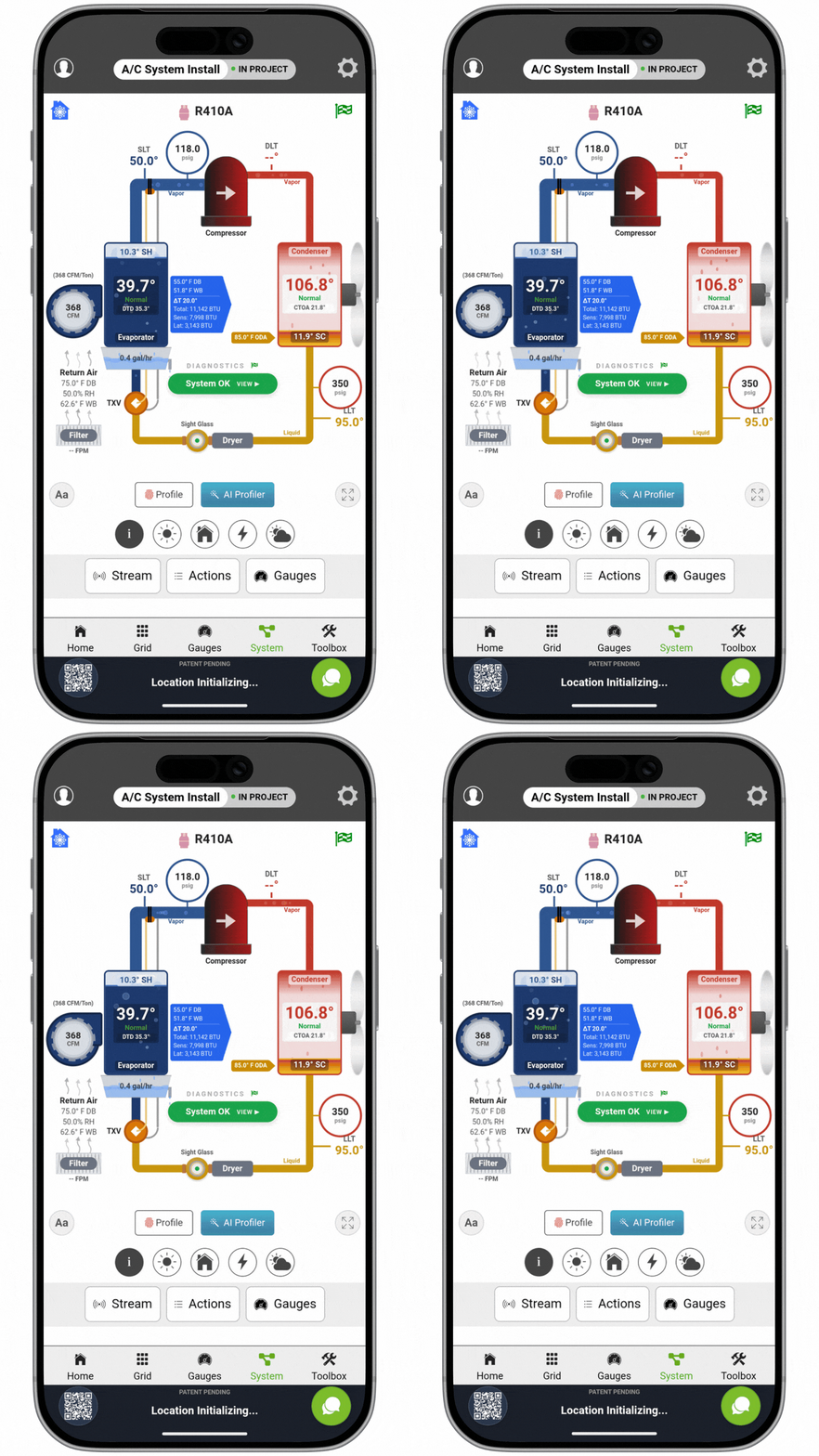
measureQuick® is used here as the HVAC system performance verification and benchmark documentation platform.

Commissioning planned. Performance Verification™ pending. Then benchmarked with measureQuick®.

The sequence matters. The system will first be commissioned and brought into its best achievable operating condition: airflow set, refrigerant performance stabilized, superheat and subcooling in range, static pressure understood, and operating targets aligned. Then the system can be benchmarked in measureQuick® so future service has a known-good baseline.
Whole Home Performance Verified HVAC case study graphic
measureQuick® benchmarking will document the system when it is performing correctly. After that benchmark is set, future service can compare against the known-good baseline instead of starting from scratch with pressure probes every time.
1. CommissionStabilize operation and complete the system setup.
2. VerifyVerify airflow, static pressure, superheat, subcooling, and operating targets.
3. BenchmarkSet the measureQuick® benchmark only after the system is right.
4. Service fasterFuture diagnostics compare to the benchmarked baseline.
mQ
measureQuick® benchmarkWill lock in a known-good operating profile after commissioning and performance verification.
SP
Static pressure and airflowWill confirm the duct system is not choking the equipment or starving rooms of designed airflow before the benchmark is set.
CAP
Capacity and operationWill validate equipment operation under real conditions so the installed system is not just “installed,” but Performance Verified™.
ModeledERI model defines the target home performance path.
BuiltThermal bypass inspection confirms the enclosure was built to match the model.
TestedBlower door, duct leakage, ventilation, and HVAC measurements will verify field conditions.
ProvenPerformance Verified™ creates documentation builders can stand behind after commissioning is complete.

Where this home beats the energy code

A quick visual map of the verified layers: enclosure, air boundary, duct delivery, IAQ, and pending measured HVAC performance.

Animated case-study graphic

The house and HVAC were designed together.

This project is being developed through the Whole Home Performance Verified™ workflow to connect the design paperwork to the actual home, installed equipment, airflow, humidity, commissioning plan, and pending measured results.

19.3%projected improvement in thermal conductance compared with the 2024 IECC prescriptive baseline.
1.0ACH50 target compared with common 3.0 ACH50 threshold language.
49projected ERI target against maximum allowed ERI 50.
R-38 Spray Foam Roof Deckconditioned attic / reduced roof load R-13 + R-10 Wall Assemblycavity insulation plus continuous exterior insulation Good Windowslower conductive and solar loads Outdoor Condenserreal split-system outdoor unit on pad Indoor Air Handlerblower, coil, filter cabinet, duct connections Supply + Return Duct Systemtrunks, branches, registers, return path Animated Airflowsupply delivery and return air path Refrigerant Line Setliquid and suction lines between units
Complete System View
A realistic HVAC and enclosure cutaway tying the roofline, walls, windows, air boundary, duct system, IAQ path, outdoor condenser, indoor air handler, airflow, and refrigerant lines back to the verified home.

Projected performance targets

Thermal UA19.3% better
Air leakageTarget air leakage: 1.0 ACH50
ERIProjected ERI target: 49
J/S/DPending verification
IAQFiltered + controlled
HVAC systemVerification pending
RooflineR-38 sealed attic spray foam strategy keeps HVAC and ducts in a more controlled environment.Thermal control
WallsR-13 cavity plus R-10 continuous insulation reduces thermal bridging.Better assembly
WindowsU-0.15 / SHGC 0.17 glazing reduces solar and conductive room-load swings.Lower load glass
Air boundaryTarget air leakage: 1.0 ACH50 target is the “one instead of three” talking point.Tighter target
DistributionSubmitted J/S/D with planned field verification ties the duct system and airflow back to the actual home.Submitted ≠ verified
IAQVentilating dehumidification, MERV 13 filtration, air-handler filtration, and optional HAVEN monitoring.Ventilate + filter + control
measureQuick® benchmarkClick here to light up the outdoor unit, indoor unit, refrigerant lines, ductwork, and airflow path planned for Performance Verification.Commissioning planned → Verification pending → Benchmark to be added
Thermal conductance19.3% better than the 2024 IECC prescriptive baseline.
Air boundaryTarget air leakage: 1.0 ACH50 target compared with common 3.0 ACH50 code-threshold language.
WallsR-13 cavity + R-10 continuous insulation.
WindowsU-0.15 / SHGC 0.17 glazing strategy.
IAQ pathwayOutdoor air passes through MERV 13 dehumidifier filtration and the air handler filter.
VerificationSubmitted J/S/D becomes verified J/S/D, with optional HAVEN on-demand IAQ visibility.
Measured HVACOutdoor unit, indoor unit, duct delivery, airflow, and operating targets are planned for Performance Verification and MeasureQuick® benchmarking.

Once the enclosure and HVAC design are connected to field verification, the equipment brand becomes less important than the process controlling it.

This is the builder-facing point: the Hagglund project uses practical GREE inverter equipment, but the outcome depends on the design, installation, controls, humidity strategy, and measured performance workflow.

Practical equipment. Premium system design.

This project does not depend on Carrier, Bryant, or another premium nameplate to carry the outcome. It uses practical GREE inverter equipment and makes it perform through design, controls, humidity management, and verification.

Value-conscious inverter equipment

2-ton first-floor and 1-ton second-floor systems selected against the actual loads.

Whole Home Performance Verified HVAC case study graphic

DESIGN VERIFIED™

Manual J/S/D ties load, equipment, duct sizing, airflow, and design intent together.

72

Ecobee controls

Smart control layer supports the design rather than trying to rescue a bad install.

Whole Home Performance Verified HVAC case study graphic

Santa Fe ventilating dehumidifier

Dedicated latent control and outdoor-air ventilation, with MERV 13 filtration at the dehumidifier.

Whole Home Performance Verified HVAC case study graphic

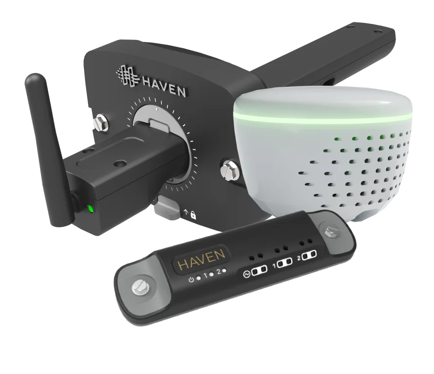
HAVEN IAQ integration

Optional on-demand IAQ monitoring and smart control visibility for comfort, particles, VOCs, and indoor conditions.

IAQ is not an add-on. It is part of the control strategy.

The ventilating dehumidifier lets the home bring in the right amount of outdoor air without letting humidity run wild. That matters in a tight, high-performance house because ventilation, filtration, humidity, and comfort all interact.

How the IAQ pathway works

  • Ventilation: outdoor air is introduced intentionally instead of relying on uncontrolled leakage.
  • Humidity control: the Santa Fe ventilating dehumidifier helps keep indoor humidity in line while ventilation is delivered.
  • Filtration: incoming supply air passes through a MERV 13 filter in the dehumidification system.
  • Second filtration layer: air is filtered again at the air handler.
  • Optional IAQ visibility: HAVEN can add on-demand IAQ monitoring and feedback for deeper control.

Builder-facing benefit

OA
Outdoor airFresh air is brought in on purpose, not by accidental leakage.
M13
MERV 13 filtrationIncoming air is filtered through the dehumidification system.
RH
Humidity controlVentilation happens without dumping moisture into the home unchecked.
AH
Air-handler filtrationA second filter layer supports cleaner recirculated air.
IQ
Optional HAVENOn-demand IAQ visibility helps verify what homeowners actually live with.

The VERIFIED™ process stack

Whole Home Performance Verified™ is the certification. The workflow is the value.

Whole Home Performance Verified HVAC case study graphic

DESIGN VERIFIED™

The home, load calculation, equipment, ducts, ventilation, and humidity strategy are reviewed as one system.

Whole Home Performance Verified HVAC case study graphic

INSTALLED PER DESIGN™

The field installation is checked against the design intent, not just against what fit in the framing.

Whole Home Performance Verified HVAC case study graphic

PERFORMANCE VERIFIED™

Commissioning and measured validation will confirm whether the system performs in the finished home.

WHPV™

Enclosure, HVAC, airflow, humidity, controls, and ERI modeling are integrated into one certification path.

Builder and homeowner outcomes

The business case is not nerd candy. It is fewer surprises after move-in.

Fewer callbacksRoom-level loads and airflow targets reduce “this room never feels right” complaints.
Better humidity controlDedicated dehumidification manages moisture independently from cooling runtime.
Less oversizing pressureLower loads and inverter equipment reduce the need for “just go bigger” thinking.
Better documentationERI modeling, J/S/D review, installation verification, and commissioning create a record.
Whole Home Performance Verified HVAC case study graphic

Code gives permission. VERIFIED™ is the path to proving performance.

Hagglund Residence is a single case study showing how practical equipment, verified design intent, better enclosure design, humidity control, and commissioning can create a more predictable builder outcome.

Whole Home Performance Verified HVAC case study graphic
Source basis: Hagglund Residence Manual J/S/D package dated May 4, 2026; Hagglund mechanical sheets M-1 through M-5 dated May 5, 2026; Hagglund 2024 IECC R-406 projected ERI report and proposed home summary dated May 17, 2026. This web page is a builder-facing case study and should be treated as representative until final field verification is complete.

Whole Home Performance Verified™ FAQ

What is Whole Home Performance Verified™?

Whole Home Performance Verified™ is a field-verification workflow that connects HVAC design, ERI modeling, enclosure testing, IAQ control, commissioning, airflow verification, and pending measured HVAC performance. This project is currently built with systems installed or being installed, with final commissioning and field verification pending.

How is Whole Home Performance Verified™ different from code compliance?

Code compliance can require submitted design documents. Whole Home Performance Verified™ is intended to verify that the submitted design, installed systems, enclosure targets, ventilation, and commissioning results match the actual home. For this project, those final results will be added after testing is complete.

What does Whole Home Performance Verified™ prove for builders?

It gives builders a documented verification pathway showing that the HVAC system, enclosure, airflow, IAQ strategy, energy model, and final field performance can be connected instead of treated as separate checklist items. This case study will be updated with final measured results after commissioning and field verification are complete.

What the Client Had to Say

What Project Collaborators Had To Say

Already Have a Plan? Submit Here To Get Started

Upload a set of plans today and let us give you a quote. Within 48 hours you will be provided a full custom quote for the design, and/or test and balance/ commissioning needs for your project. Please specify when uploading what services you would like a proposal for.

Upload a File

File(s) size limit is 20MB.

?
Enter the Captcha

By clicking here, you acknowledge and agree that HVAC 2 Home Performance may collect and use your Personal Data for purposes related to providing our services. Please click the hyperlinks to read our Privacy Policy and our Terms & Conditions .

 We will not share your information with any third parties for purposes unrelated to delivering our services. We may share your Personal Data with trusted third-party providers who assist in operating, supporting, and delivering our services, including platform providers, service partners, and other vendors. Any information not required for service delivery will not be shared with unrelated third parties.